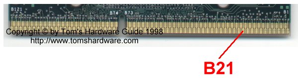
Following the Intel specification the motherboard has to automatic detect and adjust the FSB, depending on the CPU that is plugged into to system. This adjustment is done via detecting the 66/100 MHz FSB specification of the CPU by checking the logical state of CPU pin 'B21'. If B21 is logically 'high' the 100 MHz bus is chosen, if it's logically 'low' 66 MHz FSB. Intel's data sheet of the Pentium II 350 and 400 shows how this is one in particular.
On slot 1 CPU are two resistors 'R5 and 'R6'. In case of a 100 MHz FSB CPU R5 is 1 kOhm and R6 is 3.3 kOhm. CPUs with an 66 Mhz FSB (Celeron and the Pentium II 233-333) have two 0 Ohm 'resistors'.
Intel's specification is asking for a 'pull up' resistor of 200 Ohm on the motherboard, so that the 'B21' pin can be read by the clock generator. If R5 and R6 are 0 Ohm, the signal at the clock generator is logically 'low', because the pin B21 is inside the CPU directly connected to ground. In case that R5 and R6 add up to 4.3 kOhm, the signal that the clock generator gets is of course 'high', due to the 200 Ohm pull up resistor. The beauty of this situation is that due to this pull up resistor, which you can find on any BX motherboard, the clock generator will get a logical 'high' signal just as well, in case that pin 'B21' is not connected to the motherboard at all. This is all we have to take care of and the motherboard will 'believe' that a 100 MHz FSB CPU is plugged into the system.
Now how is it done?
All we want is that CPU pin 'B21' is not connected to the motherboard after we plugged in our Slot 1 CPU. A super easy and very efficient way is to simply cover pin 'B21' with a small bit of adhesive tape. To do that, have a close look at the CPU contacts first and check how wide they are, luckily 'B21' is one of the contacts in the lower row. Then cut a small maybe 1 inch long stripe from the tape which is roughly as wide as the contact. It's pretty easy if you've got a Celeron, because it hasn't got a cover, otherwise it's a bit more difficult finding the correct contact. On the Celeron it says 'B1' and 'B121' on its backside, the side where there's no chip on. In case of a Pentium II you need to look at the side which carries the hologram. In both cases it's the side of the CPU which shows the longer row of contacts to the right, the shorter row to the left, both counted from the little notch and seen when holding the CPU the way that the contacts are pointing down. Now find 'B21' by starting to count to the ELEVENTH of the lower contacts starting on the RIGHT side of the CPU. Stick the tape onto this contact and cut off the remaining part of the tape. Make sure that you are using a tape that's sticking very well and check if the tape is fixed properly on the contact so that it won't move when you plug in the CPU. If you have got an automatic motherboard and it ran at 66 MHz so far make sure that you turn down the multiplier. Now plug in the CPU and you will see that like a miracle it's now running at 100 MHz FSB. Voila!
This is how it looks on a Celeron, the Pentium II has the cover over it, but you can still access 'B21' very well without removing the cartridge.
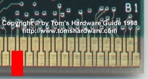
That's what it should look like after using red adhesive tape. You can afford covering a bit of the thinner contacts (B20 and B22) left and right of B21, because the metal clips of Slot 1 only touch the upper part of these two, where the contacts are wide. Be careful that the tape doesn't go up too far, but make sure that it covers all of lower B21.
It's the easiest and most efficient way of getting your Celeron or Pentium II 333 to run at 350 or 400 MHz in *ANY* BX motherboard.